

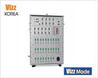
 배터리 충방전시험기
 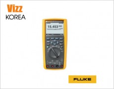 DMM287
 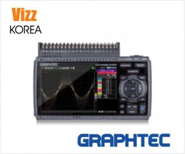 GL840M
 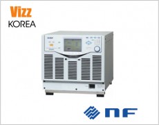 KP3000S/KP3000GS
  WT5000

제품정보

|
Strength in numbersInput channels
Bandwidth
Sample rate (all analog / digital channels)
Record length (all analog / digital channels)
Waveform capture rate
Vertical resolution
Standard trigger types
Standard analysis
Optional analysis1
Optional serial bus trigger, decode and analysis1
Optional serial compliance test1
Arbitrary/Function Generator1
Digital voltmeter2
Trigger frequency counter2
Display
Connectivity
e*Scope®
Standard probes
Warranty
Dimensions
1Optional and upgradeable. 2Free with product registration. Never let a lack of channels slow down your verification and debug process again!The 5 Series MSO offers better visibility into complex systems by offering four, six and eight channel models with a large 15.6" high definition (1,920 x 1,080) display. Many applications, such as embedded systems, three-phase power electronics, automotive electronics, power supply design, and DC-to-DC power converters, require the observation of more than four analog signals to verify and characterize device performance, and to debug challenging system issues. Most engineers can recall situations in which they were debugging a particularly difficult problem and wanted greater system visibility and context, but the scope they were using was limited to two or four analog channels. Using a second scope involves significant effort to align trigger points, difficulty in determining timing relationships across the two displays, and documentation challenges. And while you might assume that a six and eight channel scope would cost 50% or 100% more than a four-channel scope, you'll be pleasantly surprised to find that six channel models are only ~25% more than four channel models and eight channel models are only ~67% more than four channel models. The additional analog channels can pay for themselves quickly by enabling you to keep current and future projects on schedule. |

|
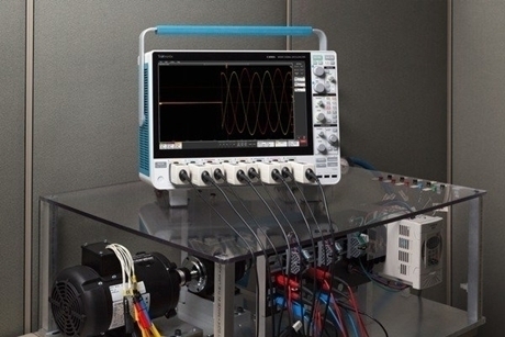
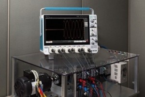
|
Voltage measurements on a three-phase motor showing the three-phase input voltages after start-up. FlexChannel®technology enables maximum flexibility and broader system visibilityThe 5 Series MSO redefines what a Mixed Signal Oscilloscope (MSO) should be. FlexChannel technology enables each of the inputs on the instrument to be used as a single analog channel or eight digital logic inputs (with TLP058 logic probe) or a spectral view of the analog input or simultaneous analog and spectral views with independent acquisition controls for each domain. Imagine the flexibility and configurability this provides. With an eight FlexChannel model, you can configure the instrument to look at eight analog and zero digital signals. Or seven analog and eight digital. Or six analog and 16 digital, five analog and 24 digital and so on. You can change the configuration at any time by simply adding or removing TLP058 logic probes, so you always have the right number of digital channels. 
|
|
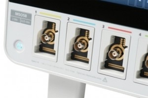
FlexChannel technology enables the ultimate in flexibility. Each input can be configured as a single analog or eight digital channels based on the type of probe you attach. Previous-generation MSOs required tradeoffs, with digital channels having lower sample rates or shorter record lengths than analog channels. The 5 Series MSO offers a new level of integration of digital channels. Digital channels share the same high sample rate (up to 6.25 GS/s) for fine timing resolution, and long record length (up to 125 Mpoints) for long time captures as analog channels. 
he TLP058 provides eight high performance digital inputs. Connect as many TLP058 probes as you like, enabling up to a maximum of 64 digital channels.
FlexChannel 2 has a TLP058 Logic Probe connected to the eight inputs of a DAC. Notice the green and blue color coding, where ones are green and zeros are blue. Another TLP058 Logic Probe on FlexChannel 3 is probing the SPI bus driving the DAC. The white edges indicate higher frequency information is available by either zooming in or moving to a faster sweep speed on the next acquisition.

Beyond just analog and digital, FlexChannel inputs include Spectrum View. This Tektronix-patented technology enables you to simultaneously view both analog and spectral views of your signal with independent controls in each domain. For the first time ever, oscilloscope-based frequency-domain analysis is as easy as using a spectrum analyzer while retaining the ability to correlate frequency-domain activity with other time-domain phenomena. Unprecedented signal viewing capabilityThe stunning 15.6" (396 mm) display in the 5 Series MSO is the largest display in the industry, providing 100% more display area than a scope with a 10.4" (264 mm) display. It is also the highest resolution display, with full HD resolution (1,920 x 1,080), enabling you to see many signals at once with ample room for critical readouts and analysis. The viewing area is optimized to ensure that the maximum vertical space is available for waveforms. The Results Bar on the right can be hidden, enabling the waveform view to use the full width of the display.

Stacked display mode enables easy visibility of all waveforms while maintaining maximum ADC resolution on each input for the most accurate measurements. The 5 Series MSO offers a revolutionary new Stacked display mode. Historically, scopes have overlaid all waveforms in the same graticule, forcing difficult tradeoffs:
The new Stacked display eliminates this tradeoff. It automatically adds and removes additional horizontal waveform 'slices' (additional graticules) as waveforms are created and removed. Each slice represents the full ADC range for the waveform. All waveforms are visually separated from each other while still using the full ADC range, enabling maximum visibility and accuracy. And it's all done automatically as waveforms are added or removed! Channels can easily be reordered in stacked display mode by dragging and dropping the channel and waveform badges in the Settings bar at the bottom of the display. Groups of channels can also be overlaid within a slice to simplify visual comparison of signals. The massive display in the 5 Series MSO also provides plenty of viewing area not only for signals, but also for plots, measurement results tables, bus decode tables and more. You can easily resize and relocate the various views to suit your application.

Viewing three analog channels, eight digital channels, a decoded serial bus waveform, decoded serial packet results table, four measurements, a measurement histogram, measurements results table with statistics and a search on serial bus events - simultaneously! Exceptionally easy-to-use user interface lets you focus on the task at handThe Settings Bar - key parameters and waveform management Waveform and scope operating parameters are displayed in a series of “badges” in the Settings Bar that runs along the bottom of the display. The Settings Bar provides Immediate access for the most common waveform management tasks. With a single tap, you can:
The Results Bar - analysis and measurements The Results Bar on the right side of the display includes immediate, one-tap access to the most common analytical tools such as cursors, measurements, searches, measurement and bus decode results tables, plots, and notes. DVM, measurement and search results badges are displayed in the Results Bar without sacrificing any waveform viewing area. For additional waveform viewing area, the Results Bar can be dismissed and brought back at any time.

Configuration menus are accessed by simply double-tapping on the item of interest on the display. In this case, the Trigger badge was double-tapped to open the Trigger configuration menu |
Touch interaction finally done rightScopes have included touch screens for years, but the touch screen has been an afterthought. The 5 Series MSO's 15.6" display includes a capacitive touchscreen and provides the industry's first oscilloscope user interface truly designed for touch. The touch interactions that you use with phones and tablets, and expect in a touch enabled device, are supported in the 5 Series MSO.
Smooth, responsive front panel controls allow you to make adjustments with familiar knobs and buttons, and you can add a mouse or keyboard as a third interaction method. |

|
상호명 : 비즈코리아 | 대표 : 김용관 | 개인정보관리책임자 : 김용관
주소 : 대전광역시 유성구 테크노 3로 65, (관평동, 한신에스메카 521호) | 사업자 등록번호 : 314-13-38818
고객상담: 070-4681-1234 | 팩스 042-333-0345 | 메일 : sales@vizz.co.kr