
제품정보


 배터리 충방전시험기
  CANSAS FLEX
  GL840M
 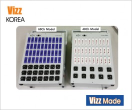 데이터로깅시스템
 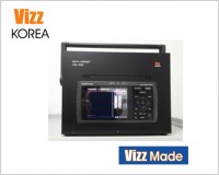 VGL-800
 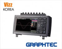 GL980
GL980 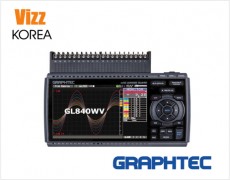 GL840WV
  B-569
B-569  B-530
B-530 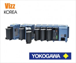 Modular GM10

Modules allow wide range of measurements
Suitable for a variety of measurements due to flexible combinations
Measurements for different applications can be added to the module. It is also possible to mix measurements by adding different types of modules.
Voltage module
(GL7-V)

Voltage/Temp. module
(GL7-M)

High-speed voltage module
(GL7-HSV)

High voltage module
(GL7-HV)

Bridge module
(GL7-DCB)

Charge module
(GL7-CHA)

Voltage output module
(GL7-DCO)

Logic/Pulse module
(GL7-L/P)

Measurements for different applications can be added to the module
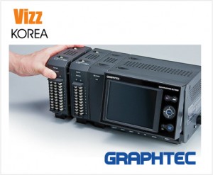
Up to 10 input/output modules can be attached to one main unit
Input module can be expanded to accommodate a wide variety of measurement.
Each of the 10 units can include a different input/output module (*1)
Up to 10 input/output modules of the same kind can be attached to one main unit(*1)
- (*1)
-
* If different types of modules are attached, the effective sampling speed of the system is to up to the fastest sampling speed among the installed modules.
When the maximum sampling speed of the module is slower than the maximum sampling speed of the fastest amplifier, signal will
be sampled with maximum sampling speed of the module. The same data is saved with the system sampling speed until new data is captured on the slower units. -
* The number of modules that can be attached is limited by the type of module.
Up to 10 modules (maximum 112ch with 7 GL7-L/P module, max 100ch with GL7-V or GL7-M module).
For Logic/Pulse module (GL7-L/P):
Maximum 7 units allowed using logic option (112ch).
Maximum 2 units allowed using pulse option (32ch).
(The mode for logic or pulse can be set for each unit.)
For Strain module (GL7-DCB):
Maximum 8 units allowed with additional two other amplifier units. (Number of channels is limited to 112ch.) -
* For the logic/pulse module, the number of channels can be limited by the selected sampling speed when the module is attached together with other amplifier modules.
1μs sampling interval: up to 8 channels
2μs sampling interval: up to 16 channels (If two modules are attached, channel #1 to #8 in each unit can be used.)
When pulse mode is used, the maximum sampling speed is the 100μs. The data will be updated every 100μs.
Maintains the maximum sampling speed
even when the number of input/output modules are increased
Maintains the maximum sampling speed even when the number of input modules for voltage or voltage/temperature are increased.
* In the high-speed voltage module and Logic/Pulse module, the maximum sampling speed varies by selected data storage device.
Up to 1120 channels can be measuring using the PC platform
Up to 10 units of the GL7000 can be connected to 1PC through LAN or USB and controlled using the software.
Up to 5 units of the GL7000 can be fully synchronized using the sync. cable
The start/stop, trigger and sampling can be synchronized in the GL7000 when they are connected by a sync. cable. The master and slave units are automatically identified.
*The sync. cable is optional (B-559). 
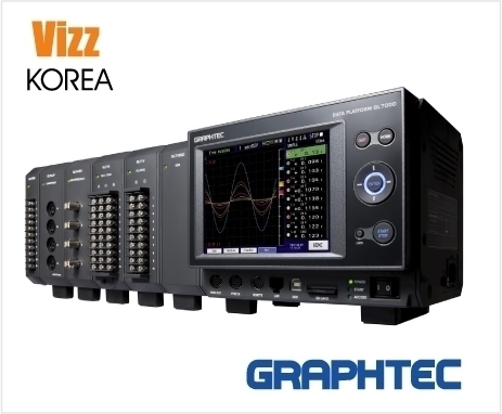
High-definition display module with touch panel enables measurement in various configuration
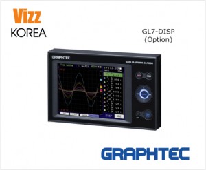
The detachable display module allows both stand-alone and embedded system configurations

Measurement settings and signal measurement can both be done without a PC by attaching the display module.
The display module can be moved to different locations for remote operation by connecting it to the main module with a LAN cable*,
it also can be embedded into the system. The module can stile be operated by the PC even when the display module is connected.
* Up to 10m using CAT5 LAN cable (straight connection)
Large easy-to-read 5.7-inch (VGA 640 x 480) high-definition LCD monitor
Utilizes a bright clear TFT color LCD monitor.
Makes it easy to read data in waveform or digital form and to check measurement parameter settings.
Y-T display
Digital display
XY display
FFT display
The display unit incorporates a touch panel system to provide convenient on-site operation
Function Menu
Easy access to each functions from listed icons.*
* It s required firmware version 2.00 or later.
Touch the icon, move to the
next setting menu screen.
The display waveform is able to
expand or shrink.
Supports multiple destinations to save the captured data according to the conditions of the measurement
Supports multiple types of storage
| Built-in RAM |
RAM is built into each modules to allow saving of up to 2 million samples for each channel. Increasing the number of channels does not decrease the data capture duration. |
| Built-in Flash memory (*1) | 4GB of Flash memory is built into the main module. Captured data can be saved directly to the flash memory when sampling speed is less than 1kS/s (1ms). Non-volatile memory (saved data is retained even if the power is turned off). |
| SD memory card (*2) | SD card slot (supports SDHC, up to 32GB) is standard on the main module. Captured data can be saved directly on the SD card when sampling speed is slower than 1kS/s (1ms). Supports hot-swap where SD memory card can be replaced during recording without any data loss. (*3) |
| SSD module (128GB) (*1)(*2) | Allows multiple recording of large amount of data to be saved when optional SSD module is used. It has a high vibration resistance and the captured data can be saved directly to the SSD when sampling is not faster than 1MS/s (1μs). (*4) |
- (*1)
- Capacity of memory device may be smaller than above depending on time of production.
- (*2)
-
The file for recording data is limited up to 4GB on firmware version 2.0 or later, 2GB on firmware version 1.6 or before.
There is function that saving data to multiple files without losing data until capturing data is stopped. - (*3)
- The hot-swap is possible when the sampling is slower than 100ms.
- (*4)
- Number of modules are limited. The storage capacity might differ by its production date.
Maximum sampling speed and the data capturing time
|
Input Module |
Storage Device | Number of units, Max. sampling speed (interval) | ||
|
Attached to 1 or 2 modules |
Attached to 3 or 4 modules |
Attached to 5 to 10 modules |
||
 Hi-speed Voltage module GL7-HSV |
Built-in RAM (2 M samples) | 1MS/s (1μs) | ||
| Built-in Flash memory (4GB) | 1kS/s (1ms) | |||
| SD memory card (32GB) (*4) | ||||
| SSD (128GB) (*4) | 1MS/s (1μs) | 500KS/s (2μs) | 200KS/s (5μs) | |
 High Voltage module GL7-HV |
Built-in RAM (2 M samples) | 1MS/s (1μs) | ||
| Built-in Flash memory (4GB) | 1kS/s (1ms) | |||
| SD memory card (32GB) (*4) | ||||
| SSD (128GB) (*4) | 1MS/s (1μs) | 500KS/s (2μs) | 200KS/s (5μs) | |
 DC Strain module GL7-DCB (*5) &  Charge module GL7-CHA |
Built-in RAM (2 M samples) | 100kS/s (10μs) | ||
| Built-in Flash memory (4GB) | 1kS/s (1ms) | |||
| SD memory card (32GB) (*4) | ||||
| SSD (128GB) (*4) | 100kS/s (10μs) | |||
 Voltage module GL7-V |
Built-in RAM (2 M samples) | 1kS/s (1ms) | ||
| Built-in Flash memory (4GB) | ||||
| SD memory card (32GB) (*4) | ||||
| SSD (128GB) (*4) | ||||
 Voltage / Temp. module GL7-M |
Built-in RAM (2 M samples) | 100S/s (10ms) | ||
| Built-in Flash memory (4GB) | ||||
| SD memory card (32GB) (*4) | ||||
| SSD (128GB) (*4) | ||||
|
Input Module |
Storage Device | Capturing time (Attached 1 module *Attached 10 modules) | ||||
|
1MS/s (1μs) |
100KS/s (10μs) |
1KS/s (1ms) |
100S/s (10ms) |
1S/s (1s) |
||
|
Hi-speed Voltage module GL7-HSV |
Built-in RAM (2 M samples) |
2sec. (2sec.) |
20sec. (20sec.) |
App. 33min. (App. 33min.) |
App. 5hrs. (App. 5hrs.) |
App. 23days (App. 23days) |
| Built-in Flash memory (4GB) | N/A | N/A |
App. 72hrs. (App. 10hrs.) |
App. 32days (App. 4days) |
App. 3269days (App. 440days) |
|
| SD memory card (32GB) (*4) |
App. 83hrs. (App. 11hrs.) |
App. 34days (App. 4days) |
App. 3495days (App. 470days) |
|||
| SSD (128GB) (*4) |
App. 4min. (N/A) |
App. 44min. (App. 6min.) |
||||
|
High Voltage module GL7-HV |
Built-in RAM (2 M samples) |
2sec. (2sec.) |
20sec. (20sec.) |
App. 33min. (App. 33min.) |
App. 5hrs. (App. 5hrs.) |
App. 23days (App. 23days) |
| Built-in Flash memory (4GB) | N/A | N/A |
App. 109hrs. (App. 17hrs.) |
App. 45days (App. 7days) |
App. 4577days (App. 715days) |
|
| SD memory card (32GB) (*4) |
App. 117hrs. (App. 18hrs.) |
App. 48days (App. 7days) |
App. 4893days (App. 764days) |
|||
| SSD (128GB) (*4) |
App. 4min. (N/A) |
App. 44min. (App. 11min.) |
||||
|
DC Strain module GL7-DCB (*5) & Charge module GL7-CHA |
Built-in RAM (2 M samples) | N/A |
20sec. (20sec.) |
App. 33min. (App. 33min.) |
App. 5hrs. (App. 5hrs.) |
App. 23days (App. 23days) |
| Built-in Flash memory (4GB) | N/A |
App. 72min. (App. 13min.) (Using 10 units of GL7-CHA modules: 10 hours) |
App. 32days (App. 5days) (Using 10 units of GL7-CHA modules: 4 days) |
App. 3269days (App. 544days) (Using 10 units of GL7-CHA modules: 440 days) |
||
| SD memory card (32GB) (*4) |
App. 83min. (App. 13min.) (Using 10 units of GL7-CHA modules: 11 hours) |
App. 34days (App. 5days) (Using 10 units of GL7-CHA modules: 4 days) |
App. 3495days (App. 582days) (Using 10 units of GL7-CHA modules: 470 days) |
|||
| SSD (128GB) (*4) |
App. 44min. (App. 6min.) |
|||||
|
Voltage module GL7-V |
Built-in RAM (2 M samples) | N/A | N/A |
App. 33min. (App. 33min.) |
App. 5hrs. (App. 5hrs.) |
App. 23days (App. 23days) |
| Built-in Flash memory (4GB) |
App. 42hrs. (App. 4hrs.) |
App. 17days (App. 2days) |
App. 1760days (App. 204days) |
|||
| SD memory card (32GB) (*4) |
App. 45hrs. (App. 5hrs.) |
App. 18days (App. 2days) |
App. 1882days (App. 218days) |
|||
| SSD (128GB) (*4) | ||||||
|
Voltage / Temp. module GL7-M |
Built-in RAM (2 M samples) | N/A | N/A | N/A |
App. 5hrs. (App. 5hrs.) |
App. 23days (App. 23days) |
| Built-in Flash memory (4GB) |
App. 17days (App. 2days) |
App. 1760days (App. 204days) |
||||
| SD memory card (32GB) (*4) |
App. 18days (App. 2days) |
App. 1882days (App. 218days) |
||||
| SSD (128GB) (*4) | ||||||
- *
-
Capturing time values are approximately. Data is saved as GBD format files. When data is saved in CSV format,
maximum sampling speed will be 10ms regardless of the captured destination and module type.
Value of the capturing time is also different from above. (Data cannot be saved to built-in RAM using the CSV format.) - (*4)
- The file size of the captured data is limited up to 4GB on firmware version 2.0 or later, 2GB on firmware version 1.6 or before.
- (*5)
- Reference recording time is for up to 8 modules. (max GL7-DCB and GL7-CHA modules is 8.)
Useful functions for reacording and replaying data
Dual-Sampling Feature *
Dual sampling speed can now be configured at the same time. While recording long intervals on the slow sampling speed, trigger set can start recording dynamic transient signals at a fast sampling speed.
* It is required firmware version 2.0 or later.
Enhanced relay recording function *
Up to 4GB data files can be recorded on a relay mode where no data loss occurs in between the files. This offers long term recording of dynamic data recording. Relay mode captures all data in between the data files eliminating data loss.
* The file for recording data is limited up to 4GB on firmware version 2.0 or later, 2GB on firmware version 1.6 or before.
Ring mode
Saves most recent data of specified number after recording stops.
Number of capturing data 1000 to 10000000 data
* When using built-in RAM, 10 to 4000000 data
Back up recording data
The data file can be created periodically for purpose of backing up data while recording it, and the file is automatically transferred to another storage
device on the unit or FTP server on the network. Backup interval: 1, 2, 6, 12, 24 hour(s)
Backup file destination: SD memory card, SSD module (optional), FTP server
Data file format: GBD (binary) or CSV (text)
* The CSV format is available with firmware version 2.10 or rater.
• Available sampling speed is the 10 ms or slower when using the CSV format.
• When the RING mode or external pulse synchronization sampling is selected for recording, the backup function is not available.
• The storage device specified as the recording destination of the measurement data can not be set as the transfer destination of the backup file.
• When backup is enabled and data file format is specified with CSV format, SD memory card exchange (hot-swapping) and RELAY recording are not available.
Other functions *
| Function | Description |
| Set time interval in between trigger repeat | Trigger repeat can not be activated based on START trigger and STOP trigger with set time interval. |
| Start/Stop Message On/Off Feature | Start/stop message will not have a on/off confirmation message. |
| SD memory card exchange | The SD card can be replaced during recording when the sampling interval is 100ms or slower. |
| Data search | Specific value (measured value, alarm point) of a particular channel in the recorded data can be searched and found automatically. |
| Movement by cursor | The cursor can be moved automatically to a specified time in the recorded data. |
| Statistical calculation with cursor | The statistical calculation (average, max, min, P-P, effective value) can be determined in between the recorded data specified by the cursor. |
Support interface frendly with the PC
Supports Ethernet and USB2.0
Ethernet (10BASE-T, 100BASE-TX) and USB2.0 (hi-speed) interface are standard.
Each interface port is located in the front of the unit for easy cable connection.
It supports the following functions.
| WEB server, FTP server function | It can be controlled by using a WEB browser, and signal can also be monitored. It supports accessing the captured data in memory device. |
| FTP client function | Captured data is periodically transferred to the FTP server for backup. |
| DHCP client function | The IP address of the GL7000 is automatically obtained from the DHCP server. |
| NTP client function | The clock on the GL7000 is periodically synchronized with the NTP server. |
| USB drive mode | GL7000 can emulate an external USB device for quick data file transfer when is is started in the USB drive mode. The file in the memory device can be transferred to the PC by drag & drop feature. |
SDK (Software Development Kit) is offered for free
Software Development Kit (SDK) is available for real time data transfer and beyond for custom application developed for your need.
- USB driver
- Manual (Main unit controls, data communication, data file, etc.)
- Sample program (in Visual C++, Visual Basic, .NET framework)
-
Key commands have been set as modules for simpler implementation with LabVIEW. Higher module has added
(Connection, Waveform Display, Digital Indicator, CSV conversion, file acquisition)
* Module type library for LabVIEW will be available in December.
상호명 : 비즈코리아 | 대표 : 김용관 | 개인정보관리책임자 : 김용관
주소 : 대전광역시 유성구 테크노 3로 65, (관평동, 한신에스메카 521호) | 사업자 등록번호 : 314-13-38818
고객상담: 070-4681-1234 | 팩스 042-333-0345 | 메일 : sales@vizz.co.kr